|
OPERATING
A
SHUNTING PUZZLE LAYOUT
|
| |
|
| |
Scale
speed
- Couplers - Setting up the game
|
|
| |
| Once you have built a shunting puzzle layout with sound baseboard
foundations and track laid down in a trackplan
arrangement which allows for the rules of your chosen
shunting puzzle and provides smooth and reliable running
of your stock, you will want to operate it - after all,
you have set up the playing board, now you want to have
fun actually playing the game - for which you may find a
few useful or interesting hints here. |
| |
|
|
The
actual rules of various shunting puzzles are
covered elsewhere (e.g. here for Inglenook
Sidings and here for the Timesaver)
- this page is all about making things move on a
shunting puzzle layout.
|
|
| |
Scale
speed
|
| |
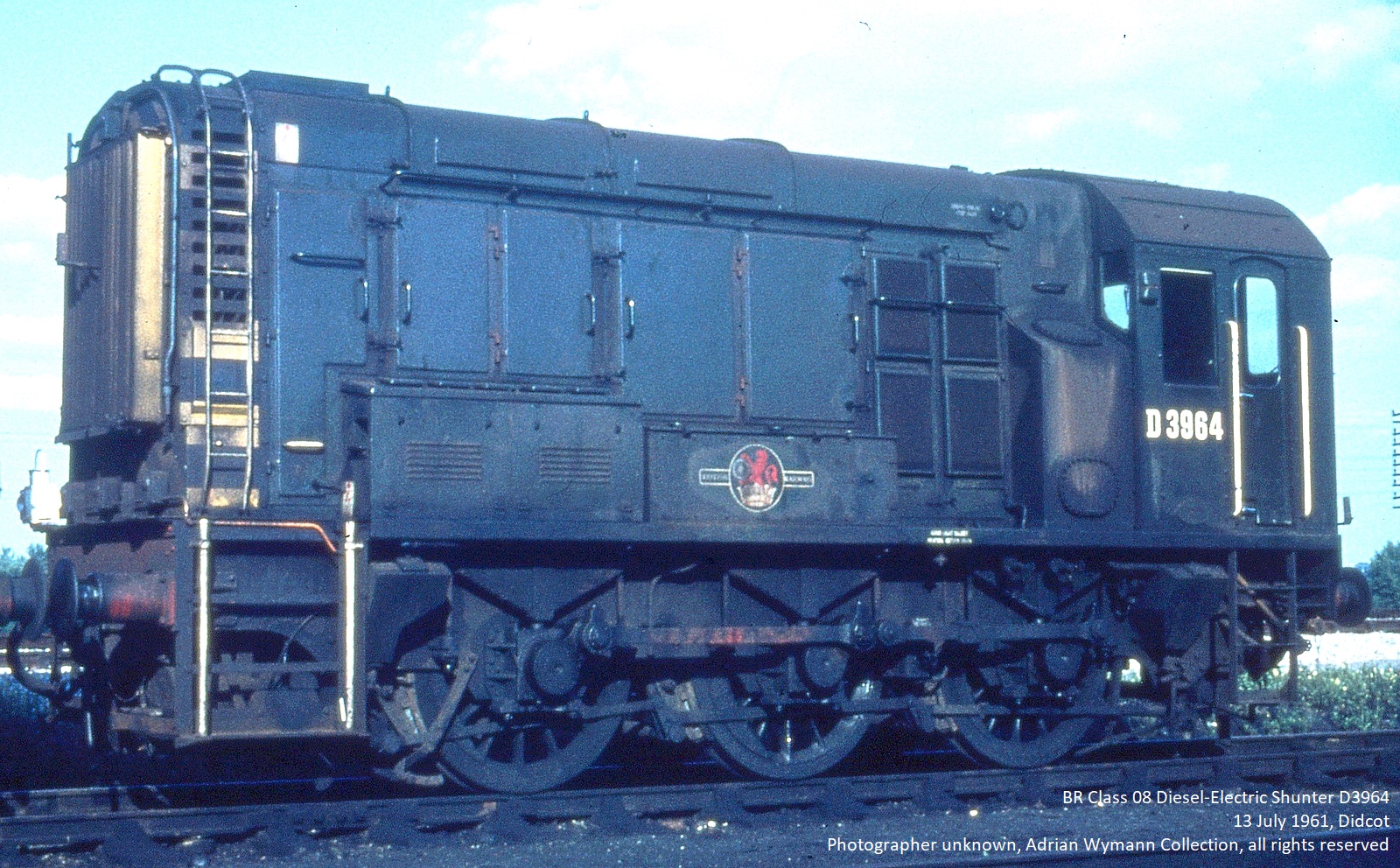
| A
shunting puzzle requires a model locomotive which runs
reliably at slow speeds. In doing so, it replicates the
prototype which doesn't allow excessive crashing and
banging simply because real railway shunting operations
try to minimize damage inflicted on rolling stock (and
the goods it carries) as well as accidents. |
| |
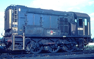
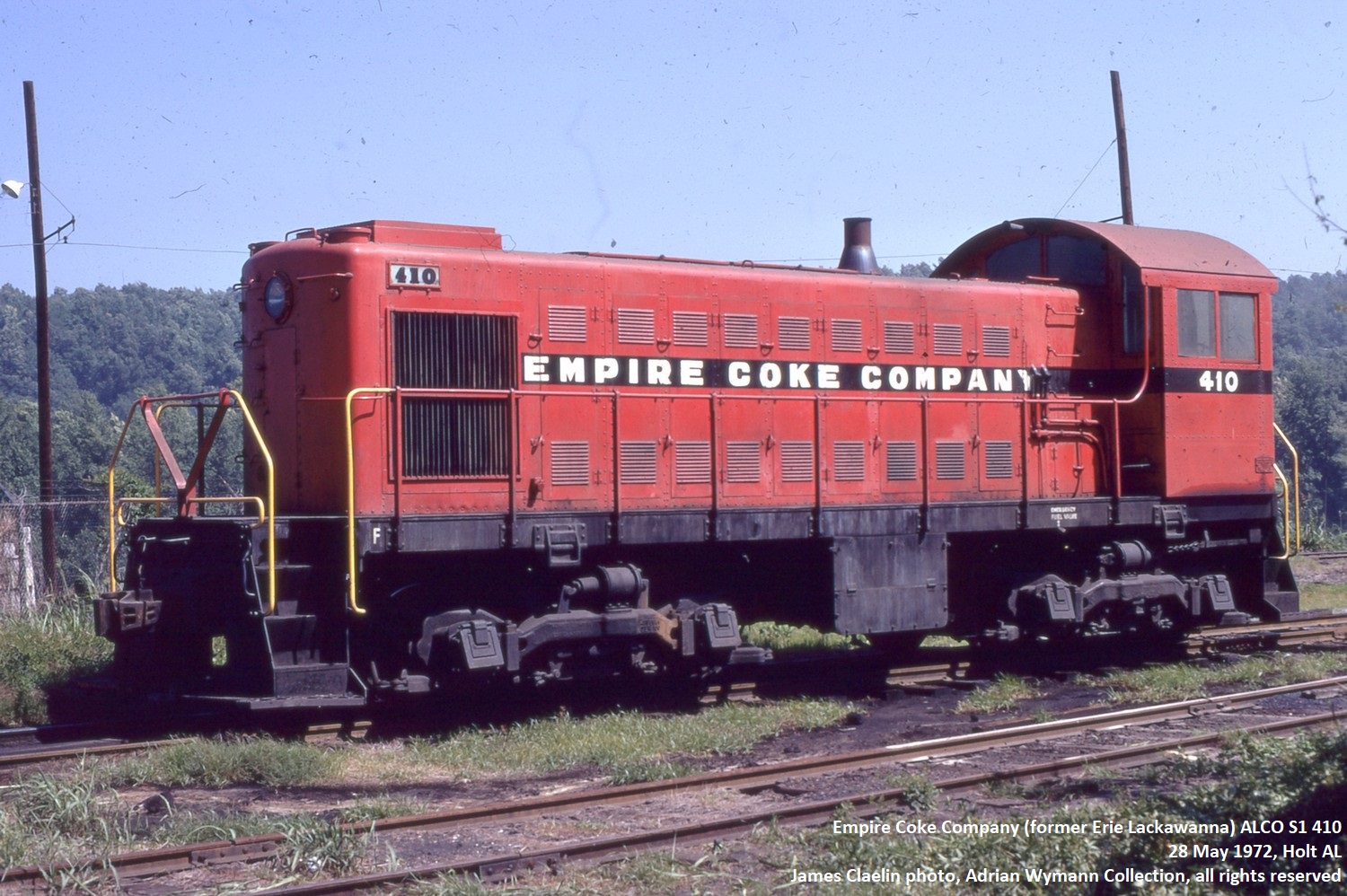
Class 08 (UK) - max speed 27mph
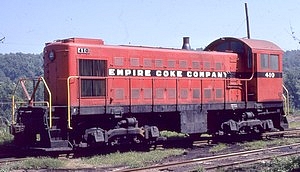
ALCO
S-1 (USA) - max speed 60mph
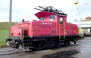
Ee 3/3 (Switzerland) - max
speed 25mph
|
|
Back
in the 1980s and early 1990s this was still a
problem as many good looking model locomotives
only ran reliably at speeds which were way too
fast. Since then, the quality of the motors and
gearing used even in low cost models has improved
markedly and flywheels are now a common feature.
If anything, it is the operator today who needs
to be reminded to slow down and run his shunting
puzzle moves at near to scale prototypical
speeds. Obviously speed ranges
of shunting locomotives vary according to
location and era, but shunting moves in yards and
on industrial tracks are usually very slow.
Sometimes this is reflected in the maximum speed
range of the prototype (at 27mph, the British Cl
08 shunter can't do anything else than trundle
along even at top speed, and the Swiss Ee 3/3
couldn't even quite keep up with that, rated at a
maximum speed of 25mph), but even an Alco S1
switcher would never do anything close to its
potential 60mph when actually performing
switching duties. "On the job",
locomotives sorting out and dropping off freight
stock (or even passenger stock) will usually be
working at speeds of 5-10mph.
The best way to track the speed of your
models is to measure a straight and level stretch
of track and then note the time the locomotive
takes to cover it. In 00/H0, a model travelling
at a scale speed of 5mph (7,5 km/h) will take 12
seconds to cover a distance of 1 foot (30 cm). If
you're travelling along at 15mph (23 km/h), it's
still 4 seconds. In N scale, a model travels 0,55
inches (1,3 cm) per second at a scale speed of
5mph (7,5 km/h).
Scale speeds usually don't come for
free, they require good equipment (both
locomotives and track) which is well maintained.
As far as track is concerned, good electrical
conductivity is a must - if it can be achieved by
regular cleaning, that's fine, if not, all
electrical contacts need to be improved and maybe
additional track feeds will be necessary - and
maybe upgrading to a better control unit will be
inevitable at some point.
If a locomotive still refuses to run
slowly even under near perfect track and power
input conditions, it will simply not qulaify as
shunting puzzle motive power. Re-motoring or
re-gearing used to be the playing field of
experienced modellers prior to the 1990s, but
today that hardly seems viable - model shunters
are mostly geared to prevent extreme non-scale
speeds and come with flywheels to ensure smooth
running even when the locomotive is crawling.
|
|
| |
| |
Couplers
|
| |
| As the word coupler
implies, its primary function is to join up individual
pieces of rolling stock and ensure that they stay
coupled, be it whilst in motion or standing still. This
effectively results in the necessary control to form and
run a train without unwanted "runaway"
incidents. The same holds
true for the model - couplers are designed to attach one
piece of rolling stock to another as securely as
possible. One specific aspect of shunting puzzle layouts,
however, is the fact that uncoupling is just as
important as coupling.
|
| |
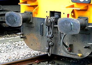
Buffer and chain coupling
(Chris McKenna)
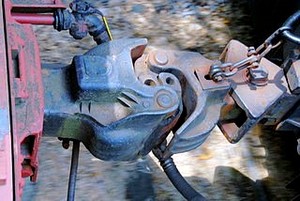
Knuckle
coupler
(Roy Smith)
|
|
The variety
in coupler types found on railway models is, in
fact, mirrored by the prototype, where several
completely different coupling systems existed and
still exist today. In Europe, the standard device
is the buffer and chain coupling, first
used by the pioneering Liverpool and Manchester
Railway in 1830. Rolling stock is coupled by hand
using what in British railway terminology is
called a screw coupling, consisting of a hook
and chain links which are secured through an
integrated turnbuckle that draws the vehicles
together.
This
coupling requires and has brought about the
typical European feature of buffers on the ends
of rolling stock an essentially provides an
arrangement which limits the slack in trains and,
with sprung buffers, absorbs shock impact.
In North America,
today's standard AAR (Association of American
Railroads) knuckle coupler essentially
goes back to Eli H. Janney who secured a patent
for his newly designed coupling device in 1873.
Thus also called a Janney coupler (or,
in the UK, where this type of coupling is used on
certain multiple units, a buckeye coupler),
it is a semi-automatic coupler which - like the
buffer and chain coupling - needs to be unlocked
manually by using a cut lever but which
- unlike the standard European coupling - couples
and locks automatically as the knuckles of two
couplers are pushed together.
This
type of coupler is also used in a number of South
American, Asian (noteably Japan and China) and
African countries as well as in Australia and New
Zealand.
The
conclusion to be drawn from the prototype is that
there is automatic coupling, but (with very few
exceptions requiring special installations) no
automatic uncoupling. The same, incidentally,
goes for model couplings.
|
|
| |
| Ever since model
trains were produced commercially the major concern with
regard to couplings was to make sure that individual
vehicules remained coupled. This certainly makes
sense from the continuous run perspective, and therefore
the vast majority of model coupling systems supplied with
ready-to-run models for a very long time seemed to assume
that once you had coupled two items of rolling stock
together you would not want them to part again. |
| |
Standard
UK tension lock coupler
|
|
No
matter whether you're looking at the (still
current) tension lock coupler (00 scale,
UK), the (now obsolete) hook and horn coupler
(HO scale, US) , the (still predominant) drop
loop coupler (HO scale, Europe), the
(standard in Europe, fading in the US) Arnold Rapido
coupler (N scale) or the (standard for
Europe) Marklin horn coupler (Z scale) -
they all have one thing in common: None of them is designed to be uncoupled
without either the famous "big hand from the
sky" or some rather unsightly uncoupling
devices which take the form of oversize ramps in
the best of cases.
The problem
from a shunting puzzle perspective is obvious:
the fun to be gained from operation is in direct
proportion to the amount of both
coupling and uncoupling involved, and if
this is a tedious process in itself, then the fun
factor immediately drops radically.
|
|
| |
| In
order to prevent this, there is the option on a DCC
controlled layout of having rolling stock equipped with
digitally controllable couplers - if these are available
or can be retro-fitted, there are no uncoupling devices
to be installed, and yet stock can be uncoupled anywhere
on the layout. On a conventional DC layout,
(electro-)magnetic uncoupling devices have proven their
worth in terms of appearance and function over a long
period of time. |
| |
| The
pioneer maker of magnetic uncoupling devices -
Kadee (R) - was specifically
founded in 1947 by twin brothers Dale and Keith
Edwards with the intention of producing a coupler
for railroad models which looked as much as the
real thing as possible and allowed for automatic
coupling and hands-off uncoupling. Today, a fair number of producers have
their own version on offer, and the principle
underlying the operation of
"magnematic" couplers (as the famous
Kadee branding goes) is well known.
Fashioned on the knuckle coupler, the
pin running down towards the track (and thus
obviously specific to the model coupling) will be
forced sideways when running over a magnet. If
there is no pulling force on the coupling, i.e.
if the rolling stock is standing still, the
knuckle will swing sideways with the pin and open
- effectively uncoupling itself.
|
|
 |
|
| |
| As the pin is still
forced outward by the magnet, pushing back into the
(open) knuckle allows for delayed uncoupling: a
piece of rolling stock can be moved to any point and
dropped off after it is uncoupled without recoupling as
long as the loco is pushing it. |
| |
 |
|
Today,
most HO, N and Z scale US prototype
models are sold with Kadee/Micro-Trains
couplers or variations thereof, some of
which were born out of necessity because
Kadee/Micro-Trains would not license
their couplers to some manufacturers.
Whilst they all look pretty much the same
at first sight - as knuckle couplers
would - some do not allow for
magnetically induced uncoupling. Rokuhan,
Japanese producer of Z scale track and
models has published a video on youtube advertising their
uncoupling track which nicely shows how
"magnematic" uncoupling works,
illustrating as a side-effect how well
suited this type of coupling/uncoupling
is for a shunting puzzle layout.
However, using Kadee
couplers with European or British outline
stock is not as straightforward as the
existence of the NEM-362 coupler pocket
would suggest, even though Kadee has a
range of different couplers suitable for
specific models. Converting these models
to this type of couplers can still be a
task requiring skill and time.
|
|
|
| |
| Just as
important as the couplers are, of course, the
uncoupling devices. They, like the couplings,
should work reliably. Most layouts running stock
which is equipped with "magnematic"
couplers use uncoupling magnets which are either
installed between (i.e. visible) or under the
running rails (i.e. out of sight). The
magnets don't look all too prototypical, of
course, but there are a number of ways to make
them less conspicuous (e.g. using them as part of
a yard pathway crossing the tracks). The magnets
which are installed below the track usually
produce a stronger magnetic field; apart from the
fact that they require a lot of advance planing
(they can't be installed once the track is fixed
down and ballasted) they also have a strong
tendency to interfere with the running of trains,
causing unwanted side-effects such as metal axles
and loco metal underframes being "locked
on".
Some
manufacturers offer set pieces of
"uncoupling tracks" which have a magnet
ready installed between the rails (e.g. Kato
Unitrack) or out of sight (e.g. Rokuhan Z scale
track which hides the magnet in the preformed
roadbed).
|
|
A Micro-Trains N scale
uncoupling magnet in place on an Inglenook
Sidings layout
|
|
| |
| The
positioning of uncoupling devices is also very crucial
for a successful shunting puzzle layout - there should at
least be enough of them to allow for all the necessary
uncoupling moves. |
| |

If
necessary or desired, an Inglenook Sidings layout can be
operated with one uncoupling device only.
It would, however, be more advisable to use three
uncoupling devices (one each at the throat of each
siding) if possible.
A Timesaver layout
requires four uncoupling devices located in specific
positions.
It won't work with less, and it doesn't need more if
couplings are used which allow for delayed uncoupling.
|
| |
| Some may want to reduce the
number of uncoupling devices to a bare minimum and will
accept having to sometimes make lengthy and not very
prototypical shunting moves such as pulling the entire
string of rolling stock from its siding in order to get
at one single freight car, while others may want to
spread a larger than needed number of uncoupling devices
around the tracks. In any case, the trackplan and
operating rules of a shunting puzzle need to be studied
carefully in order to know what the minimum requirements
for uncoupling devices are. The rest is, as so often, a
matter of personal taste. Personal taste also relates to as to
whether or not to use magnetic uncoupling. Some modellers
- and there seems to have been something of a revival of
late - seem to prefer manual uncoupling. Their argument
is that this has the advantage of being able to uncouple
wherever you need or want to without any restrictions,
rather than having to pass over a magnet first. Manual
uncoupling - often using some device which can best be
described as a "stick" (for N scale, a
toothpick will indeed do the job) - also eliminates
problems with unreliable uncoupling and the necessity to
fine tune couplers. In the end, the important thing is
that uncoupling is easy and reliable - possibly the most
important point of all when operating a shunting puzzle
layout.
|
| |
| |
Setting
up the game
|
| |
| Finally, when all is
well on the layout and running smoothly, it's time to
start playing the game. With other games, this would mean
perhaps throwing a dice or picking a card - but how do
you start a game on a shunting puzzle layout? With
both classics, Inglenook Sidings and Timesaver, you need
to know which freight car (8 of them in a standard game
of Inglenook, 5 in John Allen's original way of switching
the Timesaver) is required to go where before you can
start. Obviously, there are almost endless ways of doing
this, ranging from old tech to high-tech, but it will
always involve handling tokens which represent the
individual cars and where they are to be moved.
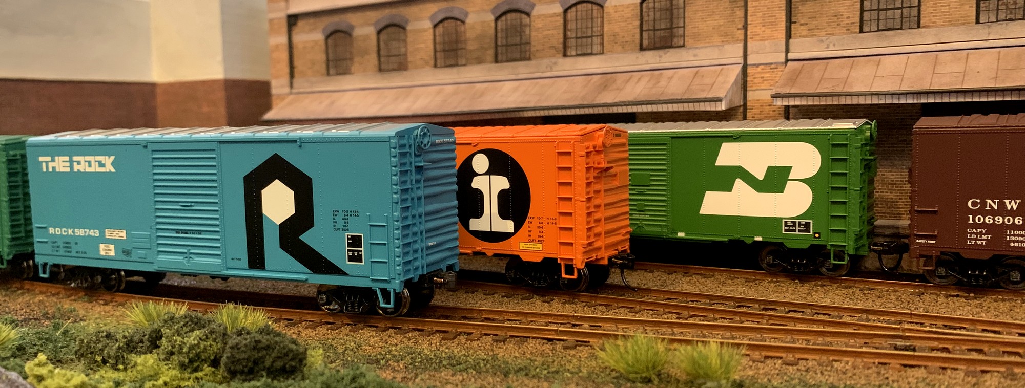
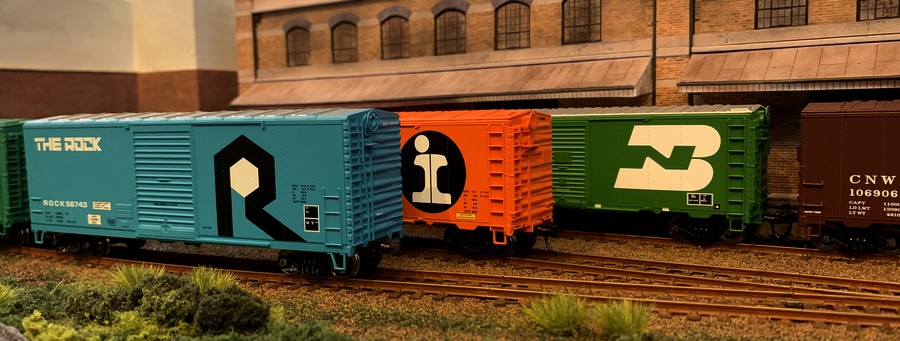
One
good idea to start with is to have distinctive looking
items of rolling stock which are easily distinguishable
(unless the shunting puzzle replicates a prototype that
used only one type of rolling stock, of course).
As
for the selection process of which piece of rolling stock
needs to go where - Alan Wright used his famous
"tiddlywink computer" (a mug which held a
tiddlywink (i.e. a token) for every piece of freight
stock on the layout) from which the required number of 5
would be drawn, and the order in which this happened at
the same time determined the order in which the cars were
required to end up. You really don't need more than that,
but I have found that using a system heavily influenced
by the classic American way of creating switching orders,
the card and waybill system, will make things unmistakeably
clear even to someone having their first go ever. The
following illustrations apply for an Inglenook Sidings
layout, but they're just as valid for a Timesaver layout
(which due to its US roots will probably feature car
cards anyway).
The
system is quite simple. On a classic Inglenook Sidings
you have 8 freight cars, each of which needs its own card
as a means of referring to this specific car. This can be
as simple or as elaborate as you care to make it -
perhaps a slightly more elaborate form could look
something like this:
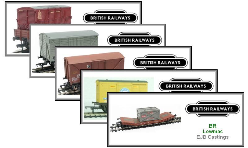
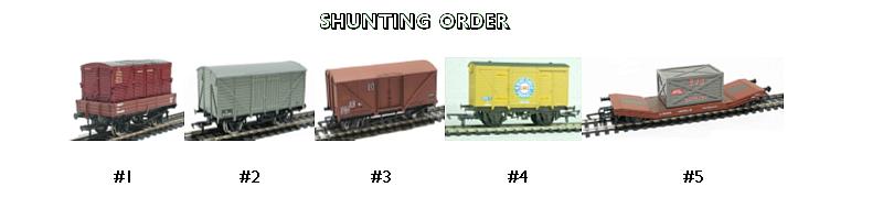
For
this US prototype Inglenook Sidings layout, every car not
only has its own card but cars have also been selected so
that the colour of the car (there's only one yellow, one
green, etc.) allows for immediate spotting of the car.
All in all, there's a total of 8 cards of identical size
which are shuffled and then the five uppermost are put
down. The order in which this takes place also serves to
determine the order in which the cars should end up.
Here,
another two cards need to be drawn, but so far you can
tell that the car which is required to be the closest to
the switcher is the the brown D&H boxcar, then the
yellow ACY boxcar, followed by the green Vermont Railway
boxcar.
It takes a bit of work to make all the cards
you'll need (though it can be done in 5 minutes if you
don't feel like having any fancy special effects), but
it's worth it, and it adds quite a bit of atmosphere to
operating a shunting puzzle layout. Naturally, the same
can be done e.g. for a UK prototype layout.
|
| |
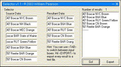
| Naturally, you could also have a computer
do the shuffling for you - which is precisely what the Inglenook
Random Wagon Selector by William Pearson will do. |
| |
 |
|
This
neat little piece of software dates from 2003 (it
will still run fine on most hardware running
Windows OS), and the screenshot shows an example
list of cars on the layout and how the Selector
produces a random list of cars in the order in
which they are to be shunted (courteousy of and
with the kind permission of Mark Kendrick, you
can still download it from this site as a
zip-file). Or, if you prefer, you can input your
rolling stock into an online random list
generator and have your shunting order made up in
your web browser by simply ignoring the last
three items in the list (one example is the List Randomizer from random.org).
|
|
| |
| |
| |
|
|
| |
Text,
pictures and illustrations not labelled otherwise are © Adrian Wymann
Page created: 11/OCT/2002
Last revised: 02/JUNE/2023
|