 |
|
| |
| |
| The layout of the
sidings beyond the station at Little Bazeley is a
variation of Alan Wright's Inglenook Sidings shunting puzzle. Shunting puzzles are rarely
geared towards prototype fidelity. Since Little
Bazeley is a fictional place, its somewhat vague
location "on the Sussex coast" simply
translates into British Rail Southern Region
territory. Also avoiding permanent indications of
a specific era allows me to use rolling stock
from any period between the mid-1960s up to
around 1992 (not at the same time, in spite of
what the title image of this page might
suggest...).
This flexibility results
not only in rolling stock that is very different
in terms of what it looks like but also in terms
of its length. Goods wagons from the 1960s
commonly have a short standard wheelbase of
10'-0" (3m), while later air-braked vans
have a wheelbase of 26'-3" (8m).
In terms of operating
Little Bazeley as an Inglenook Sidings
shunting puzzle, this means that challenges can
be set up using either the 5-3-3 formula of the original Inglenook rules or the "reduced" 3-2-2
formula, depending on the rolling stock used.
|
| |
|
| |
Shunting
Order A
(5-3-3)
for Little Bazeley Sidings
1. Form a departing train consisting
of 5 out of the 8 wagons sitting in the sidings
2. The 5 wagons are selected at random
3. The train must be made up of the 5
wagons in the order in which they are selected
|
| |
| |
Shunting
Order B
(3-2-2)
for Little Bazeley Sidings
1. Form a departing train
consisting of 3 out of the 5 wagons sitting in
the sidings
2. The 3 wagons are selected
at random
3. The train must be made up
of the 3 wagons in the order in which they are
selected
|
|
| |
| |
Couplers
|
| |
One
essential aspect of operating a shunting layout
is the choice of couplers and the uncoupling
system to go with them. Since the late 1990s
manufacturers have acknowledged the importance of
reliably working couplers by either having their
products factory-fitted with such couplers (as in
the US, where magnetic couplers in the mould of
the Kadee system are now almost standard
fittings) or by providing coupler pockets in
accordance with the NEM 362 norm, allowing
modellers to substitute the factory-fitted
couplers with a different coupler of their choice
by simply plugging this into the pocket.
|
| |
|
|
|
Ever since
developed by Tri-ang in the late 1950s, the tension
lock coupler has been the standard device
used on British 00 scale models. Consisting of a
fixed loop bar and a raisable
"fish-hook", they are foremost and
above all designed to perform automatic coupling.
This is achieved
by pushing the hook through forward motion over
the loop of the next vehicule's coupler; once the
hook drops again, the two items of rolling stock
are securely coupled and, thanks to the barbed
form of the hook, interlocked - in fact so much
so that uncoupling becomes a major
problem, even when taking stock off the rails.
|
|
| |
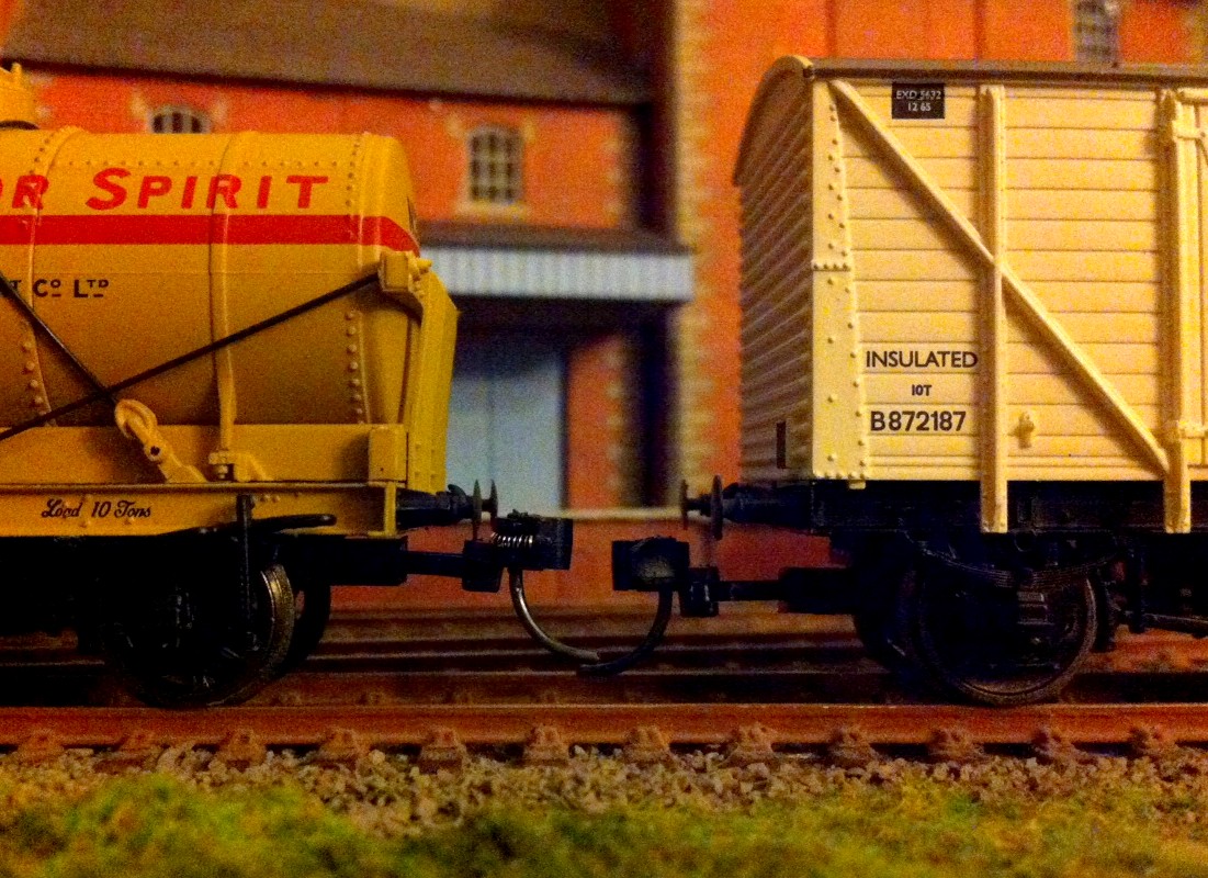
| In general, tension lock
couplers are therefore regarded as being both unsightly
and operations-unfriendly, and only suffered because
ready-to-run UK models offer no alternative. |
| |
| As can be
deduced by the way a tension lock coupler works,
uncoupling can only be achieved by way of lifting
the hook sufficiently in order to allow the loop
to pass under it again - and this will only work
when the couplers are not under tension (hence
their name), i.e. the rolling stock is standing
still. The
"classic" way of achieving this is by
using a sprung ramp between the rails. When a
train passes over it, the couplers are
interlocked through the tension and depress the
ramp. However, if the train stops, the ramp will
lift the now loose coupling hooks, splitting the
consist at this point.
The problem is that this
works fine most of the time but not all of the
time, and unwanted uncoupling increases as the
speed of a train passing over the ramp decreases
- as would of course be the case on a shunting
layout such as Little Bazeley.
The answer to this
problem is to have an uncoupling ramp which is
not permanently "active", i.e. which is
raised to push up the hooks only when rolling
stock standing over it is intended to be
uncoupled. A number of home-made systems, ranging
from basic to highly complex, have been developed
by numerous individuals, and there are even
commercially produced motorized solutions which
are push-button activated.
This allows for remote
uncoupling, but only at the exact location of an
uncoupling device, as tension lock couplers
immediately recouple once the hook is no longer
raised, making "delayed uncoupling"
(i.e. pushing an uncoupled wagon to a point
beyond the uncoupling device) impossible without
modification to the couplers.
|
|
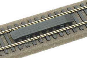
Peco uncoupling ramp (above), Gaugemaster
uncoupler (below)
|
|
| |
| This is one of the major
features and advantages of magnetic uncoupling systems such as used by the
well-known Kadee / MicroTrains couplers, which (together
with their much sleeker appearance) accounts for their
growing popularity with UK prototype modellers. This is
further heightened by the now de facto standard
of NEM 362 coupler pockets on 00 scale models which allow
for easy swapping of couplers equipped with a
swallow-tail end. Unfortunately,
the NEM 362 specifications are mostly
adhered to by manufacturers with regard to the pocket and
coupler shafts but interpreted rather loosely in terms of
the distance to the railhead (which NEM 362 sets out as
8.5mm with a tolerance of +/- 0.2mm).
|
| |
|
|
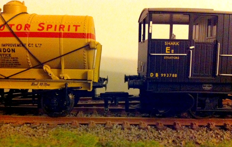
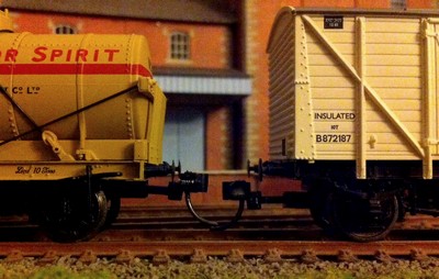
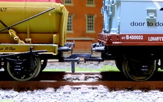
The negative effect this
can have on UK models fitted with Kadee couplers
is illustrated here: two pieces of rolling stock
from the same manufacturer (Bachmann UK) using
the very same NEM 362 Kadee couplers provide no
guarantee that the couplers will line up
correctly.
The
different heights at which the coupler pockets
are located are clearly visible in this random
example.This results in a call for some major
surgery in order to achieve reliable uncoupling
as Kadees (as well as other magnetic buckeye
couplers) tolerate little to no misalignment in
height between two couplers.
But
even if all is well adjusted, full reliability is
not guaranteed. Again, uncoupling is
usually the bigger problem, leading to the
strange "Kadee dance" when a locomotive
can be seen pulling rolling stock back and forth
over an uncoupling magnet because the two
couplings just won't separate.
|
|
| |
| This is why a growing
number of modellers remove the trip pins (which the
magnets should force sideways) on their Kadee couplers
and prefer to uncouple them manually, thus using the
couplers only for the sake of better visual appearance
(examples are the BR
Springburn Yard layout (there's a youtube video showing the pinless Kadees during
shunting moves) or the GWR/SR Hintock Branch 00 scale layout). |
| |
| One
big advantage of the Inglenook concept as
operated on Little Bazeley is that uncoupling
moves only take place in one direction (as all of
the sidings point the same way) and that the
actual position of the freight stock is of no
importance as long as the maximum number per
siding is being respected and no points are
blocked. So,
it was back to the traditional tension lock
couplers for Little Bazeley as I really could not
be bothered with the major hassle of fitting and
adjusting Kadee couplers even on as few as the 8
cars necessary for the Inglenook operation (even
less so as Kadees are the most expensive option
by far) when reliable uncoupling was not assured.
Kadees require
magnets for uncoupling, and there is an
alternative to the "activated uncoupling
ramp" approach for tension lock couplers
which makes use of magnets too.
|
|
|
|
| |
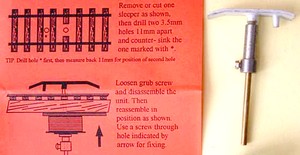
| First described by
Brian Kirby in December 2008 on rmweb.co.uk, this method modifies the
narrow Bachmann tension lock couplers (which feature a
coupling hook made of non-magnetic material) by adding a
bent iron staple to the hook. As the rolling stock passes
over a magnet, the hook is pushed upwards as the staple
is being drawn down by the magnet. |
| |
 |
|
Putting the concept to the test
using rather coarse staple samples (they are bent
so that the inward leg rises back against the
wagon floor in approximately a 45 degree angle)
the setup worked fairly reliably, especially when
using fairly large (i.e. thick) iron staples -
finer examples took more fine tuning until they
were attracted downwards by one of the two
magnets (one for each coupler) between the track.
In
comparison to any self-made raisable uncoupling
ramp (which can run into unexpected re-alignment
difficulties when lowered back to in-between the
tracks), the Kirby method has the advantage of
working faultlessly once all the couplings are
set up properly. Nut just how much time and
effort one is prepared to invest in the
"setting up" of couplers and uncoupling
devices is a matter of taste and possibly also
modelling skills.
|
|
| |
| Personally I found that adding
the staples to the counterarms of the coupling hooks took
quite some time and effort, yet reliable uncoupling on Little
Bazeley during extensive test runs was not assured. Whilst certainly due to the flaws and
shortcomings of the setup and not of the method as such,
I felt what I really wanted was an uncoupling system
which echoed the simplicity of the layout itself. |
| |
| "Simple"
and "prototypical" usually don't go
together, but in this case I found that the way
shunting was performed on British Railways in the
1960s gave me the idea on how I was going to
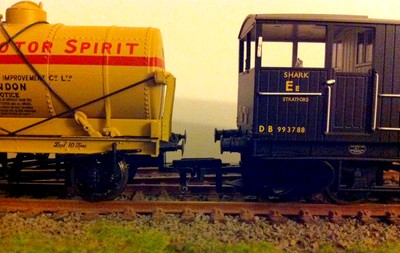
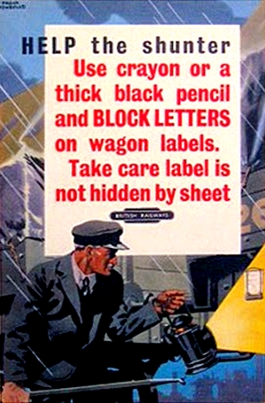
uncouple rolling stock on Little Bazeley Sidings. Now of course BR didn't
use tension lock couplers. But the main tool used when working
with hook-and-chain couplings was a shunting
pole which allowed the employee (called a shunter)
to reach between wagons to fasten and unfasten
couplings without having to physically place
himself between the rolling stock (and thus
reduced the risk of accidents). The shunter shown
in a 1950s BR in-house poster can be seen
carrying such a shunting pole in his right hand.
And this is where Sid
comes in.
Sid is, of course, short
for Sidney, the regular shunter on runs to and
from Little Bazeley Sidings. But then Sid could
also be seen as an acronym for "simple
device" - for uncoupling,
that is.
In reality, Sid is a
figure from a Preiser set of track workers
(#10418) and glued to a thin wire with a 90
degrees hook at the end which effectively acts as
a shunting pole. I got the basic - and ultra
simple - idea of the hook from a youtube video and then simply added Sid
as a slightly tongue-in-cheek decoration. Just
like the shunter on the BR poster, he uses his
pole to uncouple rolling stock at Little Bazeley
Sidings.
Most uncoupling systems
primarily try to avoid having the infamous
"big hand from the sky" appear. But the
"look no hands" approach has some very
noticeable flaws when used with tension lock
couplers. No matter whether it's the traditional
sprung ramp or a magnetic device that does the
uncoupling, rolling stock will always be
uncoupled and remain at the very same spot (i.e.
where the uncoupling device is located).
|
|
|
|
| |
| This is because delayed
uncoupling (where couplers are separated and do not
recouple if the wagons are pushed forward after the
uncoupling) is rather impractical with UK tension lock
couplers (although possible using a modified Kirby
system, as shown in this youtube
video). The ultra
simplistic way of uncoupling tension lock couplers which
Sid brings to Little Bazeley seemed much better suited
for a shunting puzzle. The only modification to the
original youtube idea needed to ensure reliable
uncoupling was to remove the hooks from the couplers
facing away from the bufferstops at the sidings - this
way, the hook only needs to lift one single hook and
instant re-coupling is minimized (which I found to be a
frequent occurence with both hooks in place).
|
| |
   |
| |
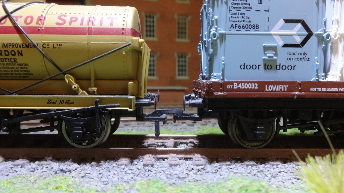
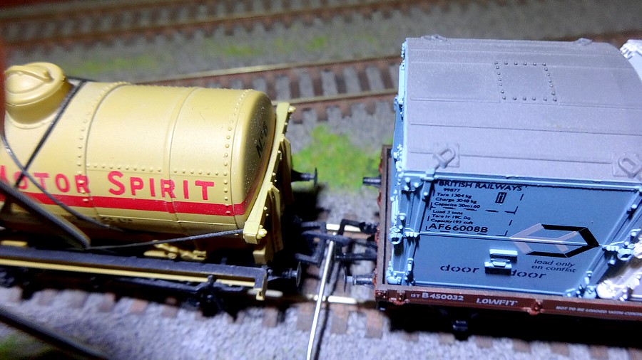
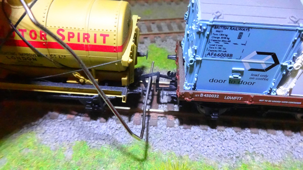
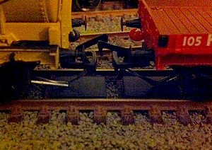
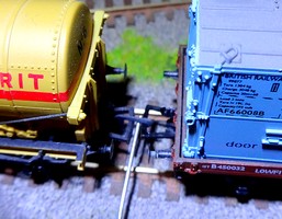
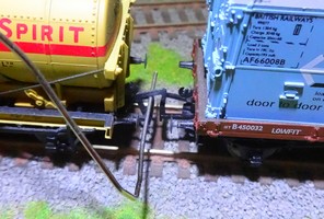
Seen here is
the single hook coupling setup (left), the paperclip wire
hook inserted between the two loop bars (centre)
and finally the uncoupling of the two goods wagons by the
simple lifting action of the wire hook (right).
|
| |
 |
|
After
initial tests I went for something just a wee bit
more elaborate - a small 1.5mm Allen wrench which
fits the purpose just perfectly. Attaching Sid
the shunter with superglue really only serves
cosmetic purposes... The big advantages of having Sid
do the uncoupling, basically, are:
a) no
visually obtrusive uncoupling devices,
b) only very minor modification of ready-to-run
stock required (removal of one single coupling
hook per wagon),
c) uncoupling is possible anywhere on the layout,
d) extremely cheap uncoupling system (as low as
the cost of a single paperclip if going for a
truly basic tool approach)
The major
disadvantage for many will, of course, be the big
hand from the sky involved in the uncoupling, but
I have found that ultimately this bothers me a
lot less than a hands-free magnetic uncoupling
system which doesn't work reliably.
|
|
 |
|
| |
|
| |
|
| |