 |
     
|
CONSTRUCTION
|
| |
| |
The construction of Little
Bazeley has been a par force effort of "trial and
error" - much of what has materialized in the end
happened to do so because something else went wrong or
didn't work at all.
Here's a brief account of how it all came together in the
end.
|
| |
|
| |
|
| |
I - PLANNING THE
LAYOUT
|
| |
| Many wise railway modellers
will tell you that the most important stage of building a
layout is planning it - and they are right. In the case
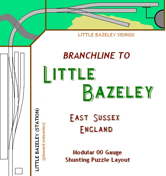
of Little Bazeley, I had the huge advantage of knowing
exactly what I wanted, namely an Inglenook Sidings
shunting puzzle, and what to avoid (by way of previous
negative experience), namely designing a layout which
would not be operable on its own and require some kind of
"add-on" in order to run it as a shunting
puzzle. Whilst both
the idea of having an Inglenook shunting puzzle as well
as giving it a name which strongly hinted at a small
layout were there right from the beginning, the original
concept centered around a much larger concept - a
"modular" layout. Planning and thinking one or
two sizes above your actual possibilities is part of the
fun, but it also shows that if left unchecked this tends
to sneak in things you didn't actually want.
|
| |
 |
|
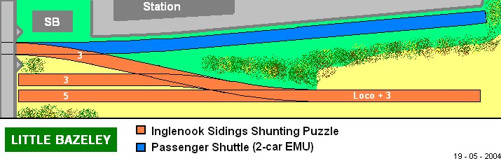
Look at
the trackplan (to the left) and you will notice
that the Inglenook Sidings "module"
would actually require a second element in order
to provide the headshunt and thus be be workable
- not good, not good at all. This was mainly due to the
fact that the initial inspiration for the layout
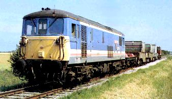
involved modern (and thus longer) stock: the
branchline to Lydd, which in the 1980s and 1990s
consisted entirely of nuclear flask transports
from the nearby Dungeness power station. Whilst
Little Bazeley Sidings was imagined to be
handling rather more conventional cargo, the
motive power on the Dungeenss branch in the late
1980s and 1990s begged to be replicated: the
wonderful (well, to me) class 73 Electro-Diesels.
|
|
| |
| Because I wanted the layout
not only to be self-contained but also to remain
portable, I knew (again from past - and failed -
attempts, such as Battersea
Sidings) that
4' (120cm) would be the maximum length. Even opting for a
ballast depot and using comparatively short wheelbase
"Dogfish" ballast hoppers (built in the 1950s),
there was no way this was going to fit into the
restricted layout dimensions actually possible and
available for this project. It became clearer and clearer
that in order to fit it all onto a 4'x1' (120cm x 30cm)
baseboard, the stock to be run on the layout would need
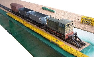
to shrink in length. This
is where coincidence (or destiny, if you prefer to look
at it that way) takes over as Bachmann was just releasing
their
model of a Class 04 diesel shunter in weathered BR green
livery and pre-TOPS numbering as D2228.
|
| |
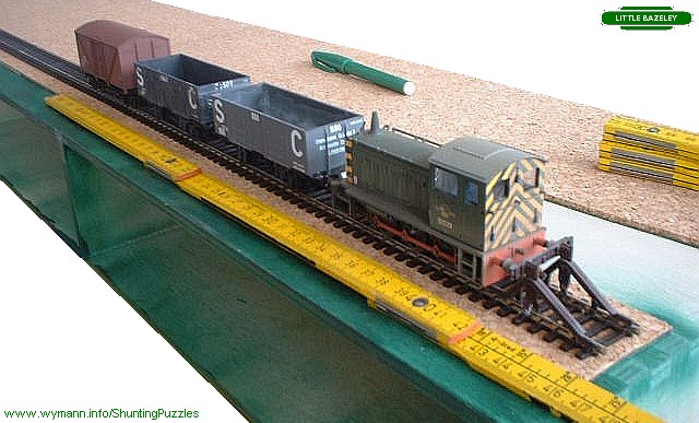
| Built by BR as the 'standard'
small 0-6-0 diesel mechanical shunter, they were
used in areas where smaller shunting locos were
needed, such as docks or areas where traffic
flows were light. When in addition I discovered
that D2228 had spent its working life along the
South Coast, matters were settled. Without much
thinking, I had thus set the time back to the mid
to late 1960s and resolved the problem with
overlong stock nicely - as proven by temporarily putting down some
lengths of track and actually measuring up the
length of rolling stock plus the newly acquired
Cl 04 shunter. That way, I knew exactly what I
got in terms of dimensions and shunting space. |
|
|
|
| |
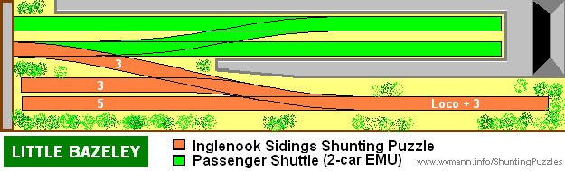
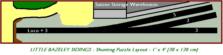
| Whilst this sorted out the
length of the track spurs required for the Inglenook
Sidings shunting puzzle, I initially tried to incorporate
a terminus station into the layout - a typically British
habit |
| |
| The
idea was to incorporate an EMU shuttle for added
variety, but the resulting station concourse
would have made for a fairly crowded affair -
which definitely was not the kind of location I
had in mind and which would carry a name such as
Little Bazeley. |
|
 |
|
| |
| So, in a
next step, the passenger station and its facilities were
reduced drastcially in scope and size by cutting down the
double track and two platform formula to just one single
trcak with adjoining platform. |
| |
 |
|
This looked and felt a lot
better and really could have passed on to the
construction stage - if not, once again, for the
fact that the EMU shuttle was a nice idea but
came with a problem: it would not be operable
without an added extension. |
|
| |
And so, I reminded myself
of C. J. Freezer's booklet 60 Plans
for Small Locations (first published in the late
1950s) and his statement concerning shunting layouts:
"it
is not obligatory to incorporate passenger facilities
into a layout, and indeed there can be very real
benefits when a small layout is designed around a
specialised service."
|
| |
| And
so - in a move to "reduce to the
max" - the plan for the layout was
revised in a way which did away with any
kind of passenger facility completely. |
|
 |
|
|
| |
| This layout and track plan
met all the criteria I had set out to start with: it was
an Inglenook Sidings type shunting layout which was both
portable and self-contained, i.e. which could be operated
without any addition to the layout. It was now definitely time to get out
a hammer and some nails.
|
| |
|
| |
| The
start to any layout construction is the baseboard, and
here the golden rule is that nothing you put on top of it
will really keep the promises it holds unless the
baseboard you use is built to last, keeps its shape and
provides you with an even surface. Originally
intending to build Little Bazeley Sidings on a
"ready made baseboard" by using a 120x28 cm
chest with drawers from IKEA (the famous
"Moppe", used by several modellers at the
time), I found that this was being discontinued just as I
was about to start the project.
|
| |
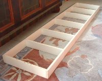
| I therefore turned to my
previous baseboard construction methods, using
10mm birch plywood for extra strength and
rigidity whilst at the same time keeping the
overall weight fairly low. The actual baseboard
top (4'x1' / 120x30 cm - a size which is still
just about portable) is set onto a framework
structure which serves as the main structural
support for the layout. Thanks to the spacers, it
is rock solid and the best insurance against
warping. At this stage, others will
still think you're actually in the process of
accomplishing some nice practical carpentry work.
|
|
 |
|
| |
|
| |
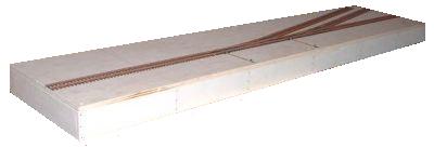
| The
track used on this layout is Peco Streamline
code 100 flextrack with medium radius electrofrog points
- my standard choice for about 20 years now. Using
Marklin Z Scale track pins sparingly, the simple track
configuration was laid down in virtually no time at all. |
| |
 |
|
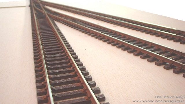
As all pieces of track are
straight I sprayed them a dark brown colour
(using an aerosol spray can) and then touched up
the side of the rails with a lighter rust colour
(using a fine artist's brush) before putting the
rails and points (which were not sprayed in order
to avoid conductivity problems - more about this
below) down. Weathered or not, the track is now
ready, and a shunting puzzle layout needs nothing
more than this to be operational. |
|
| |
| In
reality, however, few people can resist decorating this
bare gameboard... |
| |
Weathering
the track is an essential part of recreating the
atmosphere of the real railways. The colours vary
greatly on the prototype, ranging from dark,
almost black to to a very light rusty brown.
Eventually, it's a matter of taste as everything
else. However, applying weathering to the track
is best done with a subtle approach, as too much
colour can muck up the pointwork and reduce
electrical conductivity to critical levels - over
the past few years, I found that I was having
more and more trouble with electrofrog points
after painting and ballasting, as they no longer
did what they should have done, i.e. change the
polarity of the frog according to which way the
points were set.
|
|
|
|
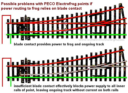
| |
| The
problem is not unkown (straight from the box the points
rely on physical contact of the switch blade and the
outer rail, so if paint gets onto this there's no
electric contact), but it seems to have plagued my
efforts more and more in recent years. |
| |
 |
|
It is such a devil of a
problem because a blade which no longer provides
effective contact with the outer rails no longer
supplies the necessary electric power to the
frog. As a result of this, the
point effectively becomes an isolating point,
with any ongoing track cut off from the necessary
electrical power supply to both rails. More often
than not, the fault can't be rectified with the
point in place. Lifting the point means lifting
the connecting pieces of track, too...
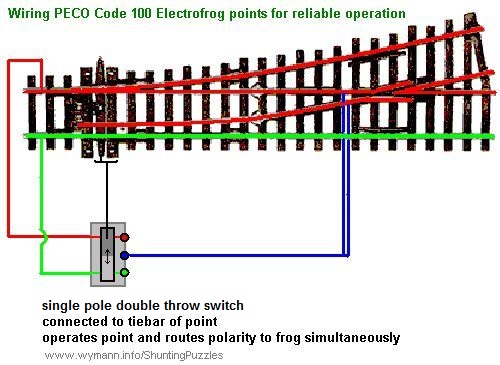
The solution to overcome this
possible problem is well-known and well-published
in the model railway press - add separate wiring
to the frog which will provide a direct means of
routing current.
|
| |
|
|
|
| Like it or not, eventually
the facts of railway modelling are such that
reliable pointwork simply is not guaranteed
straight out of the box (no matter which make you
choose), and it gets worse if you weather and
ballast your points. With
the otherwise well constructed Peco points,
ensuring reliable routing of polarity to the frog
is an easy and straightforward task (with the
code 75 points, it's even pre-installed to a
certain extent).
Because this wiring
arrangement requires the changing of the frog
polarity to take place simultaneously with the
route setting of the point, you either require a
point motor which is equipped to do this, or you
can stick with manual control and use a single
pole double throw (SPDT) on-on slide switch which
is connected by e.g. a rod to the tiebar of the
point.
|
|
|
|
| |
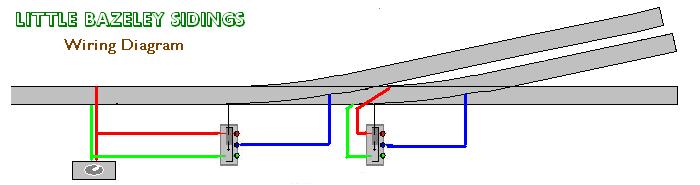
| This
way, if you slide the switch to throw the point, the
polarity routing is changed at the same time. The point
is connected to the slide switch by a piece of wire which
is attached to the tiebar and the slider of the switch. |
| |
 |
|
In order to prevent unwanted
sideway movements and to strengthen the
connection, the wire is run through a brass tube
for the length of the distance between the tiebar
and the slide. It's an easy,
dependable, and cheap method of remotely
controlling the points. At a later scenery stage,
the whole thing will be disguised with foliage
and such to make it less conspicuous.
|
|
| |
| For
the time being, Little Bazeley Sidings is wired for
analog operation (DC) despite the fact that the newer
shunters from Bachmann and Hornby are all DCC-ready. The
DC wiring on such a small and compact layout is, however,
almost as straightforward as it would be for DCC. In
fact, apart from the main feed, the only wiring in place
is for polarity switching of the point frogs, as
described above. As the points are operated manually,
there is no need for point motor wiring. |
| |
|
| |
IV - BALLASTING THE
TRACK
|
| |
| Once
the functional aspects of the track are settled, it's
time to add ballast to the weathered track - an essential
part of recreating the atmosphere of the real railways. |
| |
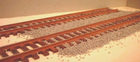
Just
as with the track itself, the colours of ballast
vary greatly on the prototype, depending on the
type of stone used and how much soil and rust is
deposited on the trackbed by traffic on the line.
Personally, I prefer the look
of grey ballast - which is not restricted to
newly ballasted tracks at all. Many yards with
light shunting traffic display light coloured
ballast, simply because there's not enough
activity to deposit tons of dirt and rust, even
over the course of a few years. The weeds,
however, are a different story...
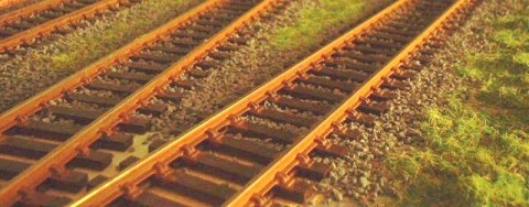
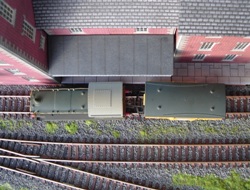
The overall effect is,
however, not only dependent on the materials used
but also on the lighting. Just how much
difference this can make can be seen from the two
views on the left: the initial stage of
ballasting (above), was photographed with the use
of artificial light, whilst the same track and
ballast at an advanced stage (below) appear to be
quite different when photographed in late
afternoon sunlight.
|
|
|
|
| |
| My
preferred make of model ballast is Woodlands Scenic
medium grey ballast, although the fine grade would
certainly be closer to scale. However, with weeds and
other green overgrowth to be added later, the appearance
to me is just fine, and it seems a lot easier to handle.
The ballast is sprinkled in place, then covered in a mist
of water and washing up liquid (also dubbed "wet
water", this brakes up the surface tension) from an
old aftershave sprayer until the ballast is quite soaked.
Immediately after this, a mixture of water and white glue
(approximately mixed at a 2:1 ratio) is carefully
dribbled onto this by employing a syringe (mine came as a
spare from the vet). The whole trackbed should be quite
white in appearance and then left to dry for a good 24
hours. After this, the ballast will be hard as concrete
(well, almost) - which is why it pays to check for
dislodged ballast (which can get onto the ties or, far
worse, cling to the sides of the rails) while everything
is still wet. |
| |
V - STRUCTURES
|
| |
| On
a small layout like Little Bazeley, different modelling
tasks start to interact very quickly, and it is a very
short cut from basic ballasting and landscaping to
setting up the first batch of planned structures. |
| |
 |
|
My plans for the sidings at
Little Bazeley were to create a small and
somewhat enclosed place, but not too sleepy and
isolated, as I wanted at least some justification
for the movement of trains. This called for some
sort of facilities to be present, rather than
just a couple of overgrown and windswept tracks
in the middle of nowhere. I
felt that that a small warehouse would be ideal,
as this allows for some very general traffic
unless specified. My structure modelling
experience stems almost entirely from plastic
kits, but for Little Bazeley I opted for card -
mainly because to me it is such a typically
British material for structure modelling that I
felt it would reinforce the
"Englishness" I was aiming to capture
with this layout.
|
|
| |
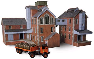
| It
would also have to be a typcially Victorian red brick
building, and I found just what I needed in the form of a
small brewery complex in the Metcalfe Models range (where
the kit carries the product code P0229), consisting of
three individual buildings. |
| |
| Obviously, certain details
which are typical for a brewery (such as roof
vents) would have to be left off in order to turn
the buildings into mere storage rather than
production facilities, but the fact that there
was precious little space behind the tracks meant
a lot of cutting and pruning anyway. 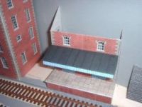 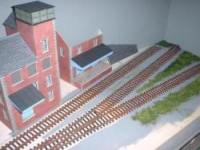
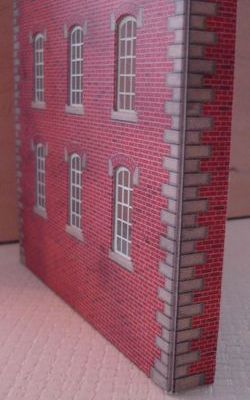
Putting card kits together is
straightforward modelling fun, and overall I
found card to be a lot easier to work with than
plastic. If you need to cut items to make them
fit a specific space, this can be done accurately
and easily - in fact, some parts of this
structure ended up being very "low
relief" indeed, as can be seen from the
building front pictured on the right.
|
|
 |
|
| |
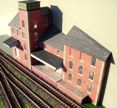
| Besides
having a charm of their own, card models these days are
pre-cut precision kits, and the brewery used on Little
Bazeley is both very sophisticated and versatile. |
| |
|
|
Just how much cutting and
pruning the kit had to endure can be seen from
the finished warehouse setup - the building on
the left of the structure is the only one built
(more or less) in its intended form. The
end result is quite pleasing in the sense that
even though the warehouse retains the overall
visual appearance of the brewery kit (and will no
doubt be recognised as such by a number of
modellers) it is at the same time unique in the
sense that it fits the specific location much the
same way a purpose built building would in real
life.

|
|
| |
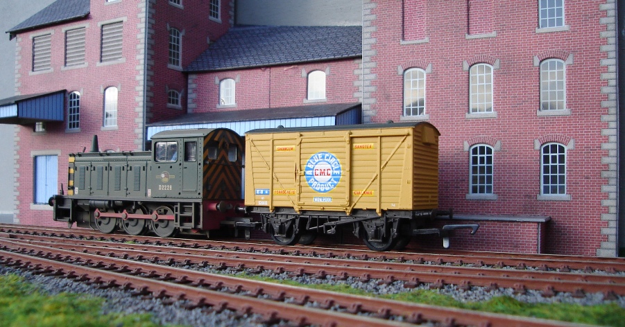
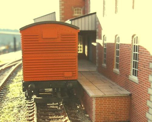
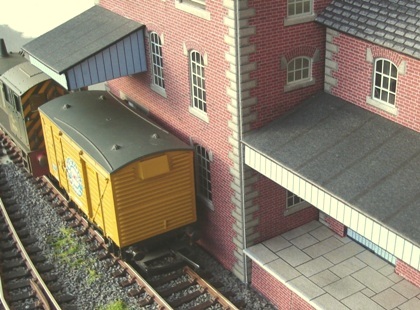
| This
type of kitbashing, however, requires extra checks on
clearances in order to ensure that all rolling stock
intended for use on the layout will clear the loading
platform edges and canopies - whilst at the same making
sure that there are no unrealistically gaping gaps
between rolling stock and (un)loading spots. |
| |
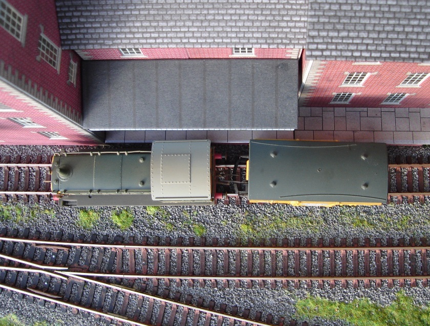
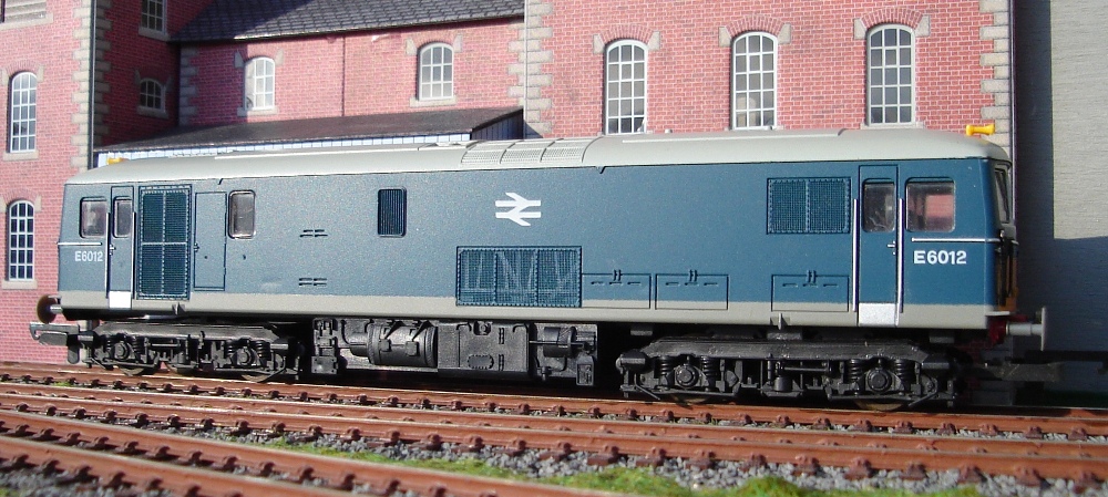
| Both the red VEA van and the
yellow 12t van are close enough to give a
convincing impression, but without fouling any
parts of the building. It is also a good idea to
make sure that clearances are compatible with the
locomotives intended for use. 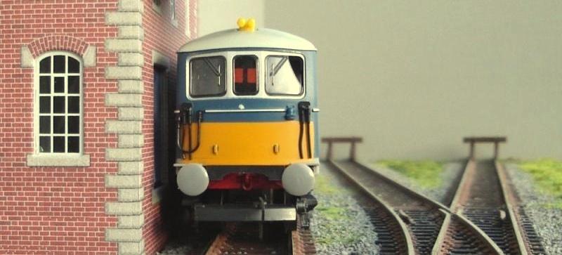
It is 1966, and BR(S)
Electro-Diesel locomotive E6012 has ventured out
to Little Bazeley Sidings on a trial run.
Clearances are tight - as they would be on the
prototype - but not too tight.
|
|
|
|
| |
VI - BASIC SCENERY
|
| |
| With
the structures all in place, the right hand side of the
layout started to look fairly complete in a basic sense. |
| |
|
|
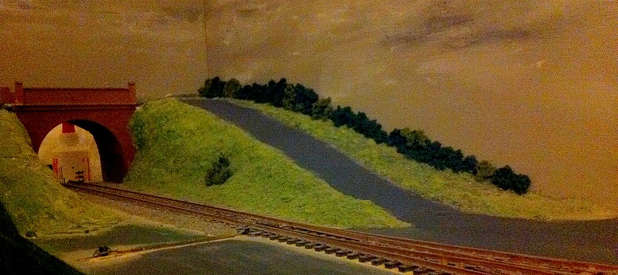
The left
hand side, however, was still a piece of
bare baseboard with un-scenicked track. The idea here was to
hide the entrance / exit of the track
(which passes through a hole in the
backdrop) by means of an overbridge from
which a road would branch off down to the
warehouse.
The bridge is an old
classic of British railway modelling.
Although the specific item used on this
layout is a 2005 production Hornby item,
it still seems to use the same mould as
employed in the 1960s by Tri-ang.
|
|
|
| |
| Picked
for sentimental reasons more than anything else, the
colouring of the plastic on this model as it comes out of
the box gives a very toy-like overall impression, but
just a simple repaint of the entire model did away with
this. |
| |
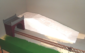
| The contours of the landscape
leading up to the bridge are modelled using a
single piece of styrofoam. It's a messy business,
but it provides a lightweight shell to work on.
This is then covered in plaster which then
receives a liberal coat of colour to seal things
up. The road surface is already
modelled into this plaster coating and only needs
appropriate colouring after this, while the rest
will receive its final touch with the sprinkling
of Woodlands Scenics scatter material.
|
|
 |
|
| |
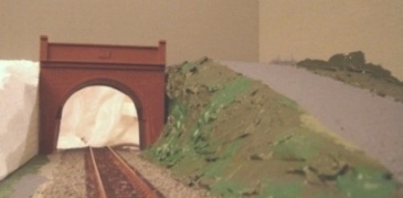
| The
realism of scenic scatter material is greatly enhanced by
mixing together two or more different colours, and the
grass used on this part of Little Bazeley is a mix of
several different types of material both in terms of
colour and texture. The final visual effect is far more
realistic than the monochrome green of just one specific
type of scatter material, |
| |
 |
|
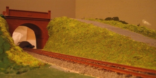
The same mix of different
shades of dark and light green scatter material
is used for grass and weeds growing onto the
tracks in front of the warehouse. 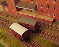
|
|
| |
| The
only thing lacking at this stage are bushes and
undergrowth, to be added on the far side of the road and
scattered along the embankment. |
| |
|
| |
| By
being "gameboards", shunting puzzle layouts
really don't require any scenicking at all - although
very few railway modellers will, of course, be able to do
completely without any scenery at all. It is, after all,
much more pleasing to the eye, and if shunting puzzle
critics point out that their operation has nothing to do
with real railways, then at least the visuals can display
some of that atmosphere. |
| |
|
|
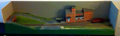
In the case
of Little Bazeley, the basic scenery
built up initially remained just that -
basic - for all of ten years, during
which any plans to improve and add
details and finish the ballasting around
the points were postponed in favour of
operation. However, a bit of spring
cleaning highlighted the unfinished state
of things, and a decision was made to
finally add some scenic details... |
|
|
| |
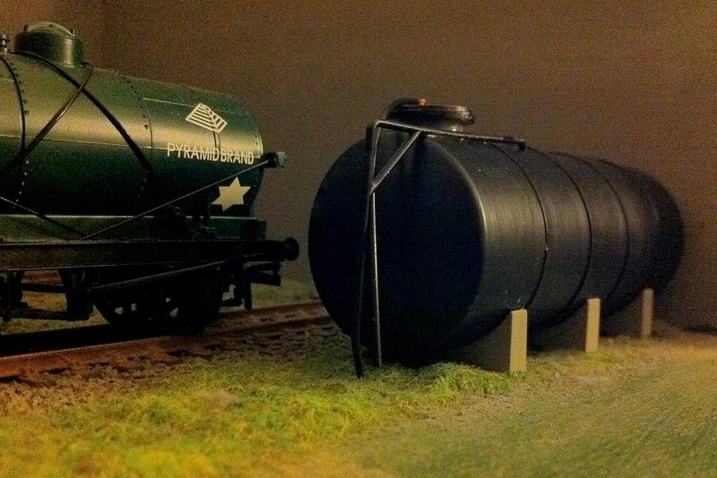
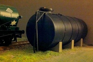
| Starting at the very end of
the line, the straight siding running parallel to the
baseboard front edge was given a storage facility which,
of course, in terms of shunting puzzle operations is
completely unnecessary and "just for show". |
| |
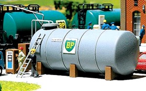
| The
small fuel tank from Faller's range of HO plastic
injection kits (article #948) seemed just right
in terms of dimensions, and changing its
German/Continental character to something more
appropriate for Little Bazeley Sidings was easy
enough. A small project in every sense of the
word, it adds a bit of storage scenery to
complement the brick warehouse - and makes the
14t tank cars seem more at home, too. |
|
  |
|
| |
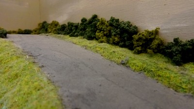
| Next, the road leading up
from the warehouse to the road bridge was resurfaced to
properly resemble a tarmac road. |
| |
|
|
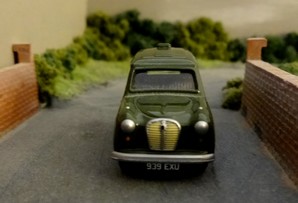
Too light in
colour previously, it now looks much more
like the feeder to a cross country B road
it would be if it actually ever existed.
At the same time, shades hinting at
clouds were applied to the previously
unfiorm grey backdrop, and a hedge of
bushes (consisting of a mix of Woodland Scenics
light green (FC145) and dark green
(FC147) bushes) added. They soften
the transition between scenery and
backdrop and are a first step indicating
just how much detail scenery makes basic
scenery come to life and look much more
refined even with the simplest of touches
added. |
|
|
| |
| |
| |
more
to come ...
|